 English
 Espaol
 Franais
 阿拉伯
阿拉伯 中文
中文 Deutsch
 Italiano
 Português
 日本
日本 韓國
韓國 български
 hrvatski
 esky
esky Dansk
Dansk Nederlands
 suomi
suomi Ελληνικ
 印度
印度 norsk
norsk Polski
 Roman
Roman русский
 Svenska
Perkins珀金斯1000柴油發動機2488618壓縮機供應商,Perkins珀金斯1000柴油發動機2488618壓縮機技術價格規格咨詢服務,Perkins珀金斯1000柴油發動機2488618壓縮機零配件供應,Perkins珀金斯1000柴油發動機2488618壓縮機售后服務中心,Perkins珀金斯1000柴油發動機2488618壓縮機,Perkins珀金斯1000柴油發動機2488618壓縮機詳細的技術參數,

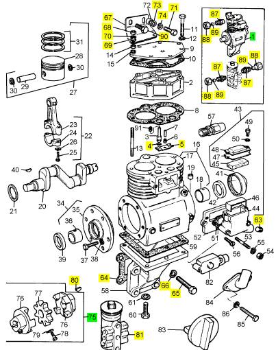
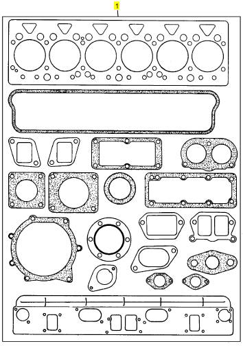
Perkins珀金斯1000柴油發動機2488618壓縮機
詳細描述
項目 零配件號碼 最新件號 描述
1 2488618 1 2488618 壓縮機
4 2 圈
5 1 鞍
63 0650594 1 0650594 栓塞
64 36866426 1 36866426 密合墊
65 2184454 4 2184454 螺拴
66 0920055 4 0920055 墊圈
67 36517726 1 36517726 托架
68 0576151 2 0576151 螺帽
69 0920003 2 0920003 墊圈
70 0920053 2 0920053 墊圈
71 0746424 1 0746424 螺旋
73 0920004 2 0920004 墊圈
74 0920054 2 0920054 墊圈
75 2581121 1 2581121 聯結器
80 0500009 1 0500009 半圓鍵
81 2488931 1 2488931 調速器
87 0206002 3 0206002 管套節
88 0576111 3 0576111 螺帽
89 0566002 3 0566002 橄欖
90 0746453 1 0746453 固定螺釘
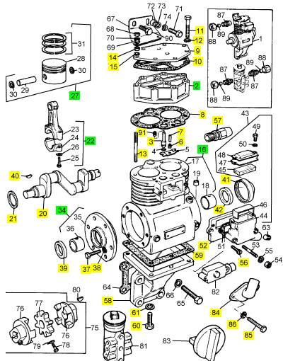
項目 零配件號碼 最新件號 描述
2 24886126 1 24886126 汽缸蓋
3 2 活塞
6 24886166 1 24886166 彈簧
7 2116110 1 2116110 銷
8 24886139 1 24888029 密合墊
9 24886122 1 24886122 蓋
10 24886123 1 24888029 密合墊
11 0748421 6 0748421 固定螺釘
12 0920053 6 0920053 墊圈
13 24886152 3 24886152 圖釘
14 0576002 3 0576002 螺帽
15 0920053 3 0920053 墊圈
16 24886149 1 24886149 氣缸
20 24886147 1 24886147 曲柄軸
21 24886115 1 24886115 墊圈
22 24886118 2 24886118 壓縮機連桿
27 24886252 2 24886252 活塞環總成 -排字工人/半徑
27 24886253 1 24886253 活塞環總成 -排字工人/半徑
34 24886138 1 24886138 蓋
37 0748413 6 0748413 固定螺釘
38 0920053 6 0920053 墊圈
39 24886113 1 24886113 密封
40 0500009 1 0500009 半圓鍵
41 24886125 1 24888029 蓋
42 24886113 1 24886113 密封
52 24886142 1 24886142 圈
56 24886111 2 24886111 螺旋
57 24886153 1 24886153 管套節
58 24886148 1 24886148 托架
59 24886124 1 24886124 密合墊
60 2222121 4 2222121 固定螺釘
61 0920053 4 0920053 墊圈
62 24886150 1 24888029 壓縮機總成
84 24886240 1 24886240 肘管
85 24886177 2 24886177 固定螺釘
86 0920052 2 0920052 墊圈
91 24887080 4 24887080 彈簧
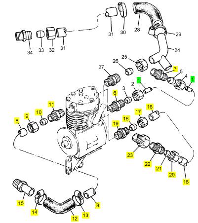
項目 零配件號碼 最新件號 描述
1 35354351 1 35354351 油管
6 0206002 1 0206002 管套節
7 0206002 1 0206002 管套節
8 34254124 1 34254124 氣管
9 0576116 1 0576116 螺帽
10 0566007 1 0566007 橄欖
11 0206008 1 0206008 管套節
12 34821118 1 34821118 水管
13 21825195 1 21825195 夾
14 21825195 1 21825195 夾
15 33552417 1 33552417 承接器
16 34574408 1 34574408 管
17 0576116 1 0576116 螺帽
18 0566007 1 0566007 橄欖
19 0206008 1 0206008 管套節
20 0576116 1 0576116 螺帽
21 0566007 1 0566007 橄欖
22 0206008 1 0206008 管套節
23 0470528 1 0470528 承接器
項目 零配件號碼 最新件號 描述
1 68298 1 U5LT1188 接合及密合墊總成
1 U5LT1188 1 U5LT1188 上部修理包
|
Gear Group (Front) - Install |
|
Installation Procedure |
|
Table 34 |
|
Required Tools Part |
|
Tool |
|
Number CH11148 27610286 CVT0015 |
|
Part Description Crankshaft Turning Tool Timing Pin (Crankshaft) Adapter |
|
Qty 1 |
|
A |
|
1 |
|
B |
|
1 |
|
NOTICE Keep all parts clean from contaminants. |
|
g01400788 |
|
Illustration 122 |
|
Contaminants may cause rapid wear and shortened component life. |
|
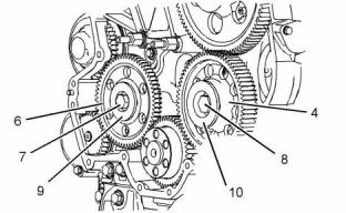
4. Follow Step 4.a through Step 4.c in order to install |
|
idler gear (6). |
|
1. Ensure that number one piston is at the top center position on the compression stroke. Refer to the Systems Operation, Testing and Adjusting, “Finding Top Center Position for No. 1 Piston”. |
|
a. Lubricate hub (9) with clean engine oil. Slide the hub into idler gear (6). Ensure that the word FRONT on the idler gear is toward the front. |
|
b. Install the assembly of idler gear (6) and hub (9) into the recess in the front housing. Ensure that the oil hole in the hub is upward. |
|
2. Ensure that Tooling (B) is installed in the flywheel housing. Tooling (B) is used to align the flywheel in the correct position. Refer to Systems Operation, Testing and Adjusting, “Finding Top Centre Position for No.1 Piston”. |
|
Note: The idler gear must be tilted during installation. |
|
c. Install bolt (7). Tighten the bolt to a torque of 240 N·m (177 lb ft). |
|
3. Ensure that all of the components of the front gear group are clean and free from wear or damage. If necessary, replace any components that are worn or damaged. Refer to Specifications, “Gear Group (Front)” for more information. |
|
5. Follow Step 5.a through Step 5.c in order to install idler gear (4). |
|
a. Lubricate hub (10) with clean engine oil. Slide the hub into idler gear (4). Ensure that the word FRONT on the idler gear is toward the front. |
|
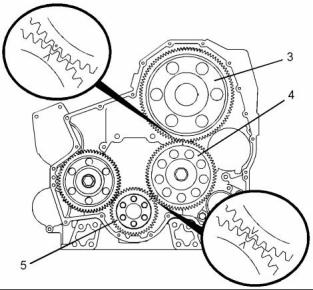
b. Align the timing marks on idler gear (4) with the timing marks on camshaft gear (3) and the timing marks on crankshaft gear (5). Refer to the Illustration 122. Install the assembly of idler gear (4) and hub (10) into the recess in the front housing. Ensure that the oil hole in the hub is upward. |
|
c. Install bolt (8). Tighten the bolt to a torque of 460 N·m (340 lb ft). |
|
g01400786 |
|
Illustration 121 |
|
6. Remove Tooling (B). |
|
7. Lubricate each gear with clean engine oil. |
|
This document has been printed from SPI². Not for Resale |
![]()

![]()
![]()
![]()
![]()
![]()
|
KENR6906 |
|
55 Disassembly and Assembly Section |
|
8. Adjust the engine valve lash. Refer to Systems Operation, Testing and Adjusting, “Engine Valve Lash - Inspect/Adjust”. |
|
9. Remove Tooling (A). |
|
End By: |
|
a. Install the front cover. Refer to Disassembly and Assembly, “Front Cover - Install”. |
|
b. Install the valve mechanism cover. Refer to Disassembly and Assembly, “Valve Mechanism Cover - Remove and Install”. |
|
i02754817 |
|
Housing (Front) - Remove |
|
g01393936 |
|
Removal Procedure |
|
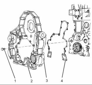
Illustration 123 |
|
1. Remove bolts (1). |
|
Start By: |
|
2. Remove front housing (2). 3. Remove joint (4). |
|
a. Remove the atmospheric pressure sensor. Refer to Disassembly and Assembly, “Atmospheric Pressure Sensor - Remove and Install”. |
|
4. If necessary, remove pump drive (3) from front housing (2). Refer to Disassembly and Assembly, “Pump Drive- Remove”. |
|
b. Remove the camshaft position sensor. Refer to Disassembly and Assembly, “Camshaft Position Sensor - Remove and Install”. |
|
c. Remove the crankshaft position sensor. Refer to Disassembly and Assembly, “Crankshaft Position Sensor - Remove and Install”. |
|
i02754818 |
|
Housing (Front) - Install |
|
d. Remove the fuel transfer pump. Refer to Disassembly and Assembly, “Fuel Transfer Pump - Remove”. |
|
Installation Procedure |
|
e. Remove the engine oil pump. Refer to Disassembly and Assembly, “Engine Oil Pump - Remove”. |
|
Table 35 |
|
Required Tools Part |
|
f. Remove the water pump. Refer to Disassembly |
|
Tool |
|
Number |
|
Part Description |
|
Qty |
|
and Assembly, “Water Pump - Remove”. |
|
Guide Stud |
|
A |
|
- |
|
2 |
|
(M8 by 80 mm) NOTICE |
|
g. Remove the engine oil pan. Refer to Disassembly and Assembly, “Engine Oil Pan - Remove and Install”. |
|
Keep all parts clean from contaminants. |
|
h. Remove the camshaft. Refer to Disassembly and |
|
Assembly, “Camshaft - Remove”. |
|
Contaminants may cause rapid wear and shortened component life. |
|
i. Remove the front gear group. Refer to Disassembly and Assembly, “Gear Group (Front) - Remove”. |
|
1. Clean the mating surfaces of the cylinder block and the front housing. |
|
j. Remove the front engine support. Refer to Disassembly and Assembly, “Engine Support (Front) - Remove and Install”. |
|
This document has been printed from SPI². Not for Resale |
![]()
![]()

![]()
![]()
|
56 |
|
KENR6906 |
|
Disassembly and Assembly Section |
|
8. If necessary, install pump drive (3) to front housing (2). Refer to Disassembly and Assembly, “Pump Drive- Install”. |
|
End By: |
|
a. Install the front engine support. Refer to Disassembly and Assembly, “Engine Support (Front) - Remove and Install”. |
|
b. Install the engine oil pan. Refer to Disassembly and Assembly, “Engine Oil Pan - Remove and Install”. |
|
c. Install the camshaft. Refer to Disassembly and Assembly, “Camshaft - Install”. |
|
d. Install the front gear group. Refer to Disassembly and Assembly, “Gear Group (Front) - Install”. |
|
e. Install the water pump. Refer to Disassembly and |
|
Assembly, “Water Pump - Install”. |
|
g01393955 |
|
Illustration 124 |
|
f. Install the engine oil pump. Refer to Disassembly and Assembly, “Engine Oil Pump - Install”. |
|
2. Install Tooling (A) to the cylinder block. |
|
g. Install the fuel transfer pump. Refer to Disassembly and Assembly, “Fuel Transfer Pump - Install” |
|
h. Install the crankshaft position sensor. Refer to Disassembly and Assembly, “Crankshaft Position Sensor - Remove and Install”. |
|
i. Install the camshaft position sensor. Refer to Disassembly and Assembly, “Camshaft Position Sensor - Remove and Install”. |
|
j. Install the atmospheric pressure sensor. Refer to Disassembly and Assembly, “Atmospheric Pressure Sensor - Remove and Install”. |
|
i02767682 |
|
Front Plate - Remove |
|
g01393936 |
|
Illustration 125 |
|
Removal Procedure |
|
3. Install a new joint (4) to the cylinder block. 4. Install front housing (2). |
|
Start By: |
|
Note: Ensure that the front housing is seated correctly on the dowels in the cylinder block. |
|
a. Remove the belt tightener. Refer to Disassembly and Assembly, “Belt Tightener - Remove”. |
|
5. Install bolts (1). |
|
b. Remove the fan drive. Refer to Disassembly and |
|
Assembly, “Fan Drive - Remove”. |
|
6. Remove Tooling (A) and install the remaining bolts |
|
(1). |
|
7. Tighten bolts (1) to a torque of 28 N·m (21 lb ft). |
|
This document has been printed from SPI². Not for Resale |